Dynamic workcell project
In conventional industrial automation, there is a fundamental split
between sensing and manipulation, as in the illustrated
``belt conveyor'' example (below, left).
In this example, widgets are brought into a robotic workcell via a
belt conveyor. The location of each widget is unknown. A camera takes
a single picture of each widget as it passes. Automated image analysis
is used to determine the exact position and orientation of each widget
relative to the conveyor belt.
From this point, there is no further sensing to guide the robot.
The velocity of the
conveyor is assumed constant, so that the robot can calculate future
positions of the widget. The actual grasp occurs some time later.
In this scenario, the environment must be carefully constrained to
ensure that nothing disturbs the widget between the time when its
pose was measured and the time when it is grasped. If the part vibrates,
slips, or is pushed to a new position, then the grasp will fail.
Similarly, the widget is assumed to be rigid and the grasp is assumed
to be firm. This means that the widget is not expected to flex, bend,
or otherwise move except as when directly manipulated by the robot.
In summary, the manipulation is ``blind''.
In the dynamic workcell project, manipulation is tightly integrated
with continuous visual sensing.
In the ``hanging chain conveyor'' example (illustrated above, right),
widgets are brought into a robotic workcell via a hanging chain conveyor.
The location of each widget is unknown. Additionally, the position
and orientation of each widget can vary as it moves down the conveyor,
due to sway.
Inside the workcell, a set of cameras takes continuous images.
Image analysis techniques locate and track the position and orientation
of each widget. As the robot initiates a grasp, it continuously
references the data supplied by the sensor system. Effectively,
the robot is able to grasp objects that are in continuous
unpredictable motion.
Once grasped, the widget might still sway or flex relative to the robot.
The sensing system will continue to provide tracking information to the
robot. This information can be used to adjust the delivery of the
manipulation.
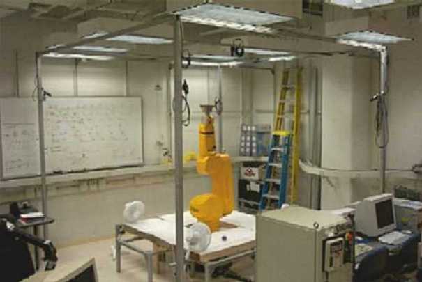
Prototype
During 2000-2001 we constructed a prototype dynamic workcell, pictured
below. The system uses all off-the-shelf components to facilitate
potential technology transfer.
The boundary of the robotic workcell is surrounded by a cube of aluminum
framing. Six cameras are attached to the framing using adjustable mounts.
The two struts on top of the cube are also adjustable. In this
configuration, a camera can be placed anywhere on top of the cube,
and at any point on the vertical edges of the cube. This leaves the
vertical planes of the workcell open for additional automation
equipment, such as conveyors.
Sitting on one side of the workcell are the robot controller, power
supplies, and computing hardware to process the video feeds.
Sponsors
The
South Carolina Commission on Higher Education
seed funded this project during 2000-2001.
Staubli Corporation
partially donated a state-of-the-art
RX-130 industrial manipulator. The U.S. Office of Naval Research
funded the exploration of this technology to naval warehousing through the
Expeditionary Logistics program.
We gratefully thank all these organizations.
People
Papers about this project
-
Y. Liu, A. Hoover and I. Walker,
"A Timing Model for Vision-Based Control of Industrial Robot Manipulators",
IEEE Transaction on Robotics, Vol. 20, No. 5, pp. 891-898, Oct. 2004.
-
I. Walker, A. Hoover and Y. Liu,
"Handling unpredicted motion in industrial robot workcells using
sensor networks", in Industrial Robot, vol. 33 no. 1, 2006, pp. 56-59.
-
Y. Liu, A. Hoover and I. Walker,
"Handling uncertainty due to the delay between complex sensing
and manipulation in an industrial workcell",
Robotica, vol. 24, no. 6, pp. 697-698, Nov. 2006.
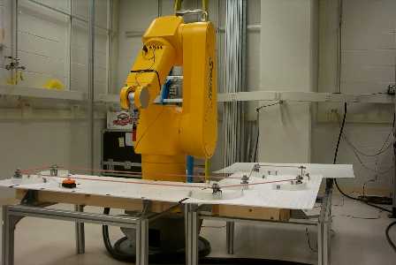
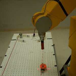
Demos
An analysis of the reaction speed (lag and latency)
of our prototype found it to be 260 ms. To measure this, we mounted a
laser in the robot's wrist, and measured the distance between
the projection of the laser and an object the robot was chasing around
a fixed conveyor (see figures below).
For perspective, this speed is comparable to a human athlete responding
to a pitched baseball or served tennis ball.
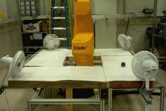
Putting this estimate (and model) to work, we implemented a demo to
catch balls moving semi-predictably. An ``air conveyor'' was constructed
(see pictures, below) that blows lightweight balls around the robot.
Note that the ball trajectory can never be predicted exactly (as would
be possible on a fixed conveyor).
Click
here to see a movie clip of how fast the system operates. This
video displays real time.
Click
here to see a movie clip of the system scooping balls off the conveyor.
This video displays real time.
Click
here to see a movie clip of the robot taking a hanger on and off a hook.
This video displays real time.
Click
here to see a movie clip of a pneumatic end effector catching and lifting
randomly moving balls. This video displays real time.